What Is an STL File? The 3D Printing Format and Its Hidden Limitations
The format that launched 3D printing in 1987 — still widely used, still fundamentally limited.
Updated Mar 2026
What Is an STL File?
STL is the format that launched the 3D printing industry. Developed by Chuck Hull and 3D Systems in 1987 — formalized in the StereoLithography Interface Specification of October 1989 — STL was designed for one specific task: preparing CAD data for the very first stereolithography machines. The name is an abbreviation of "Stereolithography," though it is sometimes retroactively called "Standard Triangle Language" or "Standard Tessellation Language."
The format works by approximating any 3D surface as a collection of triangles (triangular facets). Each triangle is defined by three vertices and an outward-facing normal vector. String enough triangles together and you can describe any shape — from a simple cube to a detailed human skull. The more triangles you use, the finer the surface detail, but also the larger the file.
Compared to 3D printing's 37-year history, STL is ancient software. Yet it remains the most widely supported 3D printing format in existence. Nearly every slicer (Cura, PrusaSlicer, Bambu Studio, Chitubox) accepts STL as the default input. Nearly every CAD program (Fusion 360, SolidWorks, Blender, Tinkercad) can export STL. This near-universal compatibility is the single reason STL has survived despite fundamental design limitations that its creators never intended for modern 3D printing.
Technical Specifications: What Is Inside an STL File
STL exists in two variants — ASCII and binary — that contain identical geometric information but package it differently. The ASCII format is human-readable plain text, starting with the keyword "solid" followed by a series of "facet" blocks. Each facet defines one triangle: a normal vector (three floats) and three vertex coordinates (nine floats). An ASCII STL for a simple cube contains 12 facets; a high-resolution model might contain millions.
Binary STL is the format you will encounter in practice. It consists of an 80-byte ASCII header (which should never start with the word "solid" to avoid confusion with ASCII STL), a 4-byte little-endian integer specifying the triangle count, and then the triangle data at 50 bytes per triangle: 12 bytes for the normal (3 × float32), 36 bytes for the three vertices (9 × float32), and 2 bytes for an "attribute byte count" (specified as zero in the standard, but non-standardly used for color data in some tools). File size formula: 80 + 4 + (50 × triangle_count) bytes.
For reference: a typical architectural model with 500,000 triangles produces a binary STL of approximately 25MB. The same model in ASCII STL would be around 200MB — roughly 8× larger. This is why 3D printing workflows almost always use binary STL.
STL coordinates are unitless. The format has no concept of millimeters, inches, or any other measurement unit. When you export a model from CAD software, the numbers in the STL file are just floating-point coordinates — it is the receiving software (or user) that interprets the units. This causes constant scaling errors in multi-software workflows.
What STL Cannot Store — The Format's Fundamental Limits
Understanding what STL cannot store is as important as understanding what it can. STL stores exactly one thing: triangulated surface geometry. Nothing more.
Color and texture: STL has no color support in the standard specification. Non-standard extensions exist (VisCAM and SolidView encode 15-bit RGB in the 2-byte attribute field; Materialise Magics encodes a single part color in the header), but these are incompatible with each other and ignored by most slicers. If your model needs color, STL is the wrong choice.
Units: As noted above, STL has no unit declaration. The format contains no way to specify whether coordinates are in millimeters or inches. This means STL files are permanently ambiguous about scale unless the exporting software documents units in a comment or the receiving software makes assumptions.
Multiple materials, print settings, and build tray information: STL is a "single surface" format. You cannot describe a multi-material print, embed slicer settings, or include support structures in an STL file. This data must be supplied separately through slicer software.
Closed, watertight geometry requirement: For 3D printing, an STL model must be "watertight" — every edge shared by exactly two triangles, no holes, no reversed normals. STL has no mechanism to enforce or verify this. Broken STL files (non-manifold geometry, intersecting surfaces, inverted normals) are among the most common problems in 3D printing workflows — which is why STL repair tools exist.
Use Cases — Who Needs STL Files and When NOT to Use Them
STL is the right choice when you need maximum compatibility with 3D printing workflows: prototyping single-color, single-material parts; sharing models with anyone in the maker or engineering community (Thingiverse, Printables, and Cults3D all use STL as the primary format); using older slicers or industrial SLA/SLS equipment that may not support newer formats.
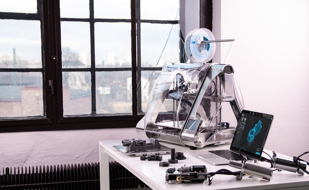
Hobbyist FDM (Fused Deposition Modeling) users: STL is the de facto standard. Virtually all FDM printers and their companion slicers support STL without any configuration. For simple PLA prints in one color, STL's limitations are largely invisible.
Engineering and manufacturing prototyping: CNC machining services, injection molding previsualization, and tolerance testing all commonly use STL because it is universally understood by machine shops' CAM software. Even though STL lacks unit information, this workflow assumes millimeter units by convention.
When NOT to use STL: Full-color or multi-material prints — use 3MF, which natively supports color, texture, and multi-material assignments. Reproducing complex prints between teams — the absence of unit information and print settings in STL files creates coordination overhead; 3MF embeds all of this. Large, high-resolution models where file size matters — 3MF uses a more compact XML + ZIP representation. Any workflow where you need to recover the original parametric design — once a CAD model is exported to STL, the design history is gone. STEP or the CAD software's native format are better choices.
Why STL Files Break — And How to Fix Them
STL "breaks" when the triangulated surface does not form a valid closed solid. The three most common problems: non-manifold geometry (edges shared by more than two triangles, or zero triangles — creates a topologically invalid mesh), inverted normals (a triangle's outward-facing normal points inward, confusing slicers about which side of the surface is "inside"), and gaps or holes (missing triangles that leave the surface open — a guaranteed print failure for FDM slicers that require manifold meshes).
These problems typically originate during CAD export (complex boolean operations can produce degenerate geometry), format conversion (converting from NURBS to STL triangle mesh introduces approximation errors), or mesh editing (manual geometry editing in tools like Blender can accidentally produce non-manifold results).
Polyvia3D's STL Repair tool uses a sequence of mesh healing operations: hole filling (connecting boundary edges to close gaps), normal consistency checking (flipping inverted faces), and degenerate face removal (eliminating zero-area triangles). For most real-world STL problems, automated repair produces print-ready files in seconds without the need for manual mesh editing.
If repair does not solve the problem, Simplify is often the next tool to reach for: reducing triangle count can resolve complex self-intersecting regions by rebuilding the mesh topology from scratch.
How to Open, View, and Convert STL Files
STL files can be opened in virtually any 3D software: Blender (free, cross-platform), Meshmixer (free, excellent repair tools), MeshLab (free, powerful analysis), Fusion 360, SolidWorks, or any 3D slicer. For quick online viewing without software installation, Polyvia3D's STL Viewer renders STL files directly in the browser.
Common STL conversions: STL to OBJ (to add color/texture support in subsequent editing), STL to GLB (for web display), STL to 3MF (to upgrade to the modern 3D printing format). All these directions are supported by Polyvia3D's browser-based converter with no file upload to servers.
Software Compatibility with STL Files
| Tool | Type | Notes |
|---|---|---|
| Cura / PrusaSlicer / Bambu Studio | Slicer | Native support — primary workflow format |
| Blender | Desktop (free) | Full import/export, repair limited to built-in tools |
| Meshmixer | Desktop (free) | Excellent repair and analysis tools |
| MeshLab | Desktop (free) | Advanced analysis, good for scientific use |
| Fusion 360 | Desktop (commercial) | Export/import, limited editing of STL meshes |
| Tinkercad | Browser | STL import and export (geometry only) |
| Polyvia3D Viewer | Browser (free) | Instant viewing, no installation |
| Polyvia3D Repair | Browser (free) | Automated repair for broken STL files |